
How to Use the Recessed Lighting Calculator
This recessed lighting spacing calculator generates a shadow-free 2D ceiling grid in 1/16″ tape-measure fractions alongside full photometric lumen and wiring takeoffs.
Step 1: Select Layout Mode and Enter Room Geometry
Configure your ceiling layout mode, room dimensions, and perimeter wall setbacks using whole inches and 1/16″ fraction dropdowns.
- Choose Mode A for a uniform proportional grid or Mode B for custom asymmetrical task and cabinet perimeter setbacks.
- Enter Room Length along the X-axis and Room Width along the Y-axis in whole inches and 1/16″ fractions.
- Set your Finished Ceiling Height and Work Plane / Countertop Height (36″ for kitchen counters or 0″ for floors).
- In Mode B, enter individual North, South, West, and East wall setbacks to align lights with 25-1/2″ countertop edges.
Step 2: Set Photometrics and IC-Rated LED Wafer Specs
Define your target room illuminance and select the physical specifications of your ultra-thin canless LED wafers.
- Enter your Target IES Room Brightness in foot-candles, such as 20.00 fc for living rooms or 35.00 fc for kitchens.
- Select your IC-Rated Canless LED Wafer Nominal Size, choosing between a 4-Inch or 6-Inch Ultra-Thin Wafer.
- Input the Lumen Output per Fixture and Wattage per LED Fixture printed on your manufacturer packaging.
- Specify the Fixture Beam Angle in degrees (such as 90.00°) and the Spacing-to-Ceiling Height Ratio (such as 0.50).
Step 3: Configure Rough-In Electrical and Retail Packaging
Specify your circuit cable gauge, switch homerun distance, and retail multi-pack box sizes for accurate material rounding.
- Select your NM-B Romex Cable Gauge & Circuit Amperage, such as 14/2 NM-B Romex for a 15A circuit.
- Enter the Homerun Distance from Wall Switch to First Wafer in whole inches and 1/16″ fractions.
- Set the Vertical Slack, J-Box Loop & Joist Routing Waste percentage to cover NEC box loops and framing runs.
- Choose your Retail LED Wafer Multi-Pack Box Size (such as a 6-Pack Contractor Box) and Retail NM-B Romex Spool Length.
- Enter the continuous LED wattage capacity for your 150W CL LED Dimmer Switch Rating.
Step 4: Enter Unit Prices, Electrician Labor, and Contingency
Input local hardware store prices and electrician per-fixture rates to compare DIY material costs against turnkey installation.
- Enter the cash-register Price per LED Wafer Multi-Pack Box, Price per NM-B Romex Spool, and Price per 150W CL Dimmer.
- Input the Licensed Electrician Base Rate per Light for standard open-stud rough-in installations.
- Select a Ceiling Access & Retrofit Difficulty Multiplier, such as 0.00x for DIY or 1.35x for an existing finished ceiling.
- Add an Unforeseen Contingency Buffer percentage to cover hidden framing blocks, drywall patches, or old junction boxes.
Understanding Your Recessed Lighting Results
The calculator organizes your results into four actionable cards covering photometric lumen demand, 2D tape-measure offsets, beam geometry, and retail costs.
Card 1: Photometric Lumen Demand & Final Fixture Count
This card functions as a dedicated lumens calculator, matching your room square footage and target foot-candles against a balanced row-by-column ceiling grid.
Card 2: Exact 2D Ceiling Grid Layout & Tape-Measure Offsets
Every linear output is converted into whole inches and reduced 1/16″ tape-measure fractions so you can snap chalk lines without converting decimals.
Card 3: Beam Spread, Hole Saw Specs & Electrical Load
This section verifies cone overlap at countertop height using beam trigonometry while sizing your hole saw, dimmer switch count, and Romex wire run.
Card 4: Retail Shopping List & Project Cost Breakdown
Raw fixture and wire totals are rounded up to whole contractor boxes and spools to calculate your true hardware store receipt and labor estimate.
- Whole Multi-Pack Boxes & Romex Spools: Rounds fixture counts and wire footage up to whole 1, 4, 6, or 12-packs and 50, 100, or 250-ft spools.
- Total Cash-Register Material Cost: Multiplies whole wafer boxes, Romex spools, and dimmer switches by their respective retail unit prices.
- Licensed Electrician Installation Labor: Multiplies Total Installed Lights by the base labor rate and your selected Ceiling Access & Retrofit Difficulty Multiplier.
- Subtotal, Contingency & Total Cost: Combines materials and labor into a base subtotal, applies your contingency percentage, and outputs the final project budget.
CONTRACTOR QUICK CHECKLIST: DYNAMIC GEOMETRY & NEC WARNINGS
• Drywall Bridge Guard: Maintain at least 4″ of uncut drywall between hole cutouts to prevent gypsum bridge fractures.
• Upper Cabinet Clearance: Never set Mode B cabinet walls closer than 18″ or 12″ deep upper doors will clip the beam.
• Zero Shadow Striping: Keep X and Y pitch below your maximum spacing limit with positive beam overlap at the counter.
• NEC 80% Load Limit: Cap continuous lighting loads at 1,440.00 W on 14/2 (15A) or 1,920.00 W on 12/2 (20A) circuits.
Tools & Materials Needed
Layout & Drywall Cutting Tools
Use precision layout and dust-controlled cutting tools to transfer your 2D grid onto the ceiling without damaging joists.
• Cross-Line Laser & Chalk Box: Self-leveling green plumb/cross-line laser level and a 100-ft blue chalk line reel.
• Tape Measure & Stud Finder: 25-ft × 1-1/4″ standout fractional tape measure and a deep-scan magnetic/radar stud finder.
• Carbide Grit Hole Saw & Dust Bowl: 4-1/4″ or 6-1/4″ recessed lighting carbide grit hole saw with clear silicone dust shield.
• Drill/Driver & Drywall Jab Saw: 18V/20V brushless 1/2″ chuck drill/driver and a 6″ pointed drywall jab saw.
Wire Fishing & Electrical Tools
Equip yourself with insulated stripping and fishing gear to pull NM-B cable cleanly across closed ceiling bays.
• Fiberglass Fish Rods & Tape: 15-ft glow-in-the-dark splinter-guard fiberglass wire fishing rod kit and 50-ft steel fish tape.
• Flexible Joist Auger Bit: 54″ × 3/4″ flexible spring-steel wire-pulling auger bit for blind-drilling closed ceiling joists.
• Romex Ripper & Wire Strippers: 12/2 and 14/2 NM-B outer-jacket cable slitter and 10–20 AWG forged wire strippers.
• Voltage Tester & Lineman Pliers: CAT IV 1000V non-contact voltage tester pen and 9″ high-leverage lineman’s pliers.
Primary Fixtures, Romex Cable & Control Specifications
Match your shopping list against these standard U.S. electrical supply house specifications before roughing in your ceiling circuit.
Hardware, Fasteners & Rough-In Consumables
Stock these code-compliant connectors, staples, and patching materials to complete your rough-in and ceiling trim-out.
• Push-In Lever Wire Connectors: 3-port UL-listed transparent lever splicing connectors (such as Wago 221-413) for 12–24 AWG solid/stranded conductors.
• NM Cable Clamps & Staples: 3/8″ trade-size snap-in plastic NM-B box connectors and 1/2″ insulated plastic Romex framing staples.
• J-Box Mounting Screws: #8 × 3/4″ pan-head self-tapping wood screws for securing remote LED driver boxes to ceiling joists.
• Fireblock Foam & Drywall Compound: Orange UL-classified fireblock expanding foam sealant for top-plate holes and 45-minute setting-type joint compound.
Always check local building codes and HOA guidelines before starting.
How many recessed lights do I need?
Multiply your room square footage by your target IES foot-candles (20.00 fc for living rooms, 35.00 to 50.00 fc for kitchens) and divide by the lumen output per fixture (typically 900.00 lumens), then arrange the count into a balanced grid spaced no further apart than half your ceiling height.
Enter your exact room length, width, ceiling height, and cabinet setbacks into the calculator above to generate your row-by-column fixture count and 1/16″ chalk-line measurements.
Recessed Lighting Project Overview
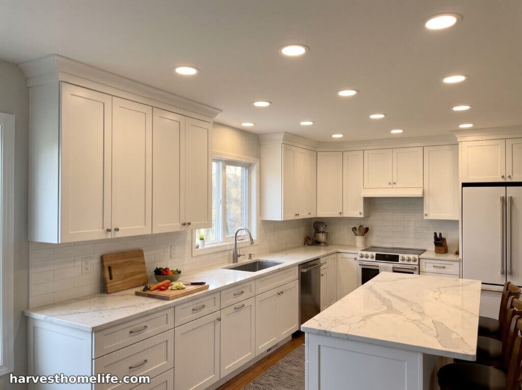
Using our recessed lighting calculator eliminates the two biggest layout mistakes in residential remodeling: guessing fixture counts by rough square footage and dividing kitchen ceilings in half without accounting for 24″ base cabinets. This recessed lighting layout calculator solves both your photometric lumen demand and exact 2D tape-measure coordinates before you drill a single hole.
Why Asymmetrical Mode B Beats Basic Half-Pitch Formulas
Standard uniform grids (Mode A) work well in open living rooms and bedrooms where perimeter wall offsets equal half the can-to-can pitch. In kitchens, however, placing lights by room midpoints drops fixtures behind your shoulders, casting a dark body shadow across the cutting board.
Switching to Mode B locks custom perimeter setbacks on all four walls independently—such as 25-1/2″ over L-shaped countertops—before solving the remaining interior span in 1/16″ fractions. It also verifies work-plane beam overlap and sums serpentine NM-B Romex runs into whole retail spools.
Worked Field Example: 15′-0″ × 12′-0″ Kitchen Task Layout (Mode B)
Below is a complete numerical trace for a 180″ × 144″ (180.00 sq. ft.) kitchen with a 108″ (9′-0″) ceiling, 36″ counters, 25-1/2″ North and West counter setbacks, 31-1/2″ South wall offset, and 36-1/2″ East walkway offset using 6″ (900.00 lm, 12.00 W, 90.00° beam) wafers.
Field-Tested Recessed Lighting Layout, Setback & Rough-In Reference
Use these contractor photometric tables, cabinet setback rules, and NEC rough-in standards to verify your ceiling layout before cutting drywall.
What Are the Recommended IES Foot-Candles, Wafer Sizes, and Color Temperatures by Room?
The Illuminating Engineering Society (IES) defines 1.00 foot-candle (fc) as 1 lumen of light landing on 1.00 sq. ft. of surface area. Before snapping an ultra-thin wafer into the ceiling, set the 5-CCT selector switch on the remote driver box to match the room’s function and verify a 90+ CRI rating so wood grain, food, and skin tones render naturally.
Choose 4″ ultra-thin wafers (4-1/4″ hole saw cutout, 4-3/4″ trim OD) for 8′-0″ ceilings, hallways, bathrooms, and task zones where a crisp architectural aperture looks best. Step up to 6″ ultra-thin wafers (6-1/4″ hole saw cutout, 6-3/4″ trim OD) in large kitchens, living rooms, or ceilings 9′-0″ and higher to deliver wider flood coverage with fewer ceiling penetrations.
How Do You Lay Out a Ceiling Grid Around Ceiling Joists, HVAC Ducts, and Upper Cabinets?
Start by measuring out from your reference walls using the Card 2 offsets and snapping perpendicular X and Y chalk lines across the drywall. In kitchens, standard base cabinet boxes measure 24″ deep with a 1-1/2″ countertop overhang (25-1/2″ total), while upper wall cabinets measure 12″ deep.
- The 25-1/2″ Countertop Setback: Snapping your chalk line 25-1/2″ from the wall places the wafer 13-1/2″ in front of 12″ upper cabinets, clearing open doors and dropping light straight onto the counter edge.
- Straddling 16″ On-Center Joists: Unlike 5-1/2″ to 7-1/2″ deep cans that must fit inside a 14-1/2″ joist bay, 1/2″ to 5/8″ thick IC-rated wafers sit flush with 1/2″ or 5/8″ drywall right under a 1-1/2″ wood joist.
- Remote Driver J-Box Placement: When a wafer straddles a joist or low-profile flex duct, tuck the 1-3/8″ to 1-1/2″ deep steel driver J-box into the adjacent open cavity and secure it per local code.
- Spring Clips & 4″ Drywall Bridges: Mousetrap torsion springs extend 1″ to 1-1/2″ past the hole perimeter, requiring at least a 4″ uncut drywall bridge between holes so your carbide grit hole saw never blows out the gypsum.
What Are the NEC Rough-In Rules for Daisy-Chaining LED Wafers and Derating Dimmer Switches?
Daisy-chaining recessed wafers requires strict compliance with National Electrical Code (NEC) conductor length, continuous circuit loading, and multi-gang dimmer heat dissipation standards. Removing aluminum heat-sink fins to fit dimmers into a multi-gang wall box reduces their continuous LED wattage capacity.
CONTRACTOR QUICK CHECKLIST: PRE-CUTTING & ROUGH-IN VERIFICATION
• Lock CCT Switches First: Set every remote driver box to 2700K, 3000K, or 4000K before snapping wafers into the ceiling.
• Probe with a Pilot Wire: Push a 1/16″ stiff wire near your center mark before running the hole saw to spot hidden pipes.
• Clamp Every NM-B Entry: Install 3/8″ snap-in strain relief connectors on every J-box knockout with 1/4″ of sheath inside.
• Derate Multi-Gang Dimmers: Lower the dimmer wattage input to 125.00 W or 100.00 W whenever snapping off side heat-sink fins.
Frequently Asked Questions
Q. How far apart should can lights be?
A. Divide your finished ceiling height by 2 (0.50 spacing ratio) for shadow-free lighting. For a standard 9′-0″ (108″) ceiling, space recessed lights no more than 54″ (4′-6″) apart on-center, and offset the outer rows 27″ (2′-3″) from open perimeter walls so the 90.00° beam cones overlap at the work plane.
Q. How far should recessed lights be from cabinets?
A. Set kitchen recessed lights 25-1/2″ out from the back wall. Standard base cabinets measure 24″ deep with a 1-1/2″ countertop overhang (25-1/2″ total), while upper cabinets are 12″ deep. A 25-1/2″ center setback positions the light 13-1/2″ in front of upper cabinet doors, preventing door clipping and head-cast counter shadows.
Q. How much does a licensed residential electrician charge to install recessed lighting in an existing ceiling?
A. A licensed residential electrician charges a base labor rate of $125.00 per fixture for open-stud rough-ins (1.00x multiplier), rising to $168.75 per light (1.35x multiplier) when blind-fishing 14/2 NM-B Romex through closed joists in an existing finished ceiling, or $206.25 per light (1.65x multiplier) in insulated vaulted ceilings, plus materials.
Planning your next project? Browse our master hub of Free DIY Home & Garden Calculators to get instant material lists, spacing math, and budget estimates.